Fixed the Street Fighter II CRT!!

A month and a half ago, I got a free SF2 machine. However, it was putting out a green screen. Since that time I’ve been repairing the display and today I finally had a real breakthrough.

Somebody at work had a B&K 467 Rejuvenator device and came by to my office today. He gave the ol’ K7000 monitor on my arcade machine a nice rejuvenation and now the SFII arcade machine is functional!

In the end, there was definitely a short in the green gun, which we cleared using the rejuvenator. There was also likely a small short in the blue gun. The blue gun was fairly weak, so we boosted that up. The red gun was very weak, so that improved the most. The rejuvenator device really came through in this one and in the end I was right about it being a CRT issue and not some issue with the chassis.

The next step is to replace the joysticks and buttons. The left joystick is missing a switch, so the player can’t walk forward. Both joysticks are a little worse for wear in general (squeaky and hard to rotate), so I’m going to replace them both. I also need to replace the fluorescent bulb in the marquee. After that gets replaced, it’s gonna look super classy.

If you haven’t been following along, check out all the blog posts about this arcade machine that I got for free.

K7000 Chassis Repair: Installed a cap kit, new flyback, and new HOT

arcademachine

If you’re just joining us, a few weeks ago, I got a free, yes, free, Street Fighter II: Champion Edition arcade machine. I turned it on and found there was no sound and the screen was all green. Since then, I’ve determined the original arcade board (the PCB) was bad. However, the screen remains green, so I’ve been doing research to find out what exactly I need to fix on the CRT monitor to get it working again.

My monitor chassis is a Wells Gardner K7000 and on the advice of several people who have worked on monitor repair before, I was told to replace the capacitors, the flyback, and the Horizontal Output Transistor, i.e. the HOT.

Over the course of two late nights, I made the repairs. (Boy, I learned a lot. I’ll have a separate blog post on some tips for replacing the flyback and caps.) I put the monitor chassis back in the arcade machine today to see the results of my hard work.

Here she is after getting a new flyback, caps, and HOT. I cleaned up the PCB and wires as well, so she’s looking real clean:

installed

The good news is nothing blew up. I can also adjust the the screen enough that I can actually see some gameplay! The flyback is working much smoother. The old one had high pitched hiss. When compared against the YouTube video I took of this a few weeks ago, you can see that there are no more wavy vertical lines on the right. I suspect the replaced capacitors fixed this up.

The bad news is that it’s still green and still has horizontal lines. 🙁 Actually it’s green with hints of blue. If I crank up the brightness or contrast, I see even more blue. This was what I was seeing before the repairs as well.

Here are a couple of pics:

titlescreen

fireball

In the end, I am happy with my work doing the cap kit and flyback repair. I can’t believe I actually did it. However, there’s still more work to be done, so stay tuned.

What I’ve learned about CRTs in a week

It’s been about a week since the last update. Since that time, I’ve asked a few experts about the display. A few folks have mentioned replacing the “cap kit”, the HOT, and possibly the flyback transformer. Others mentioned checking the monitor chassis. A week ago I had no idea what any of this meant. Today I do.

Here’s what I know:

First of all, the monitor chassis is the printed circuit board on which the monitor components live. This sits underneath the CRT, the cathode ray tube, and larger display tube. Usually, if these old displays go bad, it’s because of a bad component on the chassis.

If you want to fix the monitor, you typically need to order new parts and replace the old ones on the chassis. I’ll get to the parts in a minute, but first a word about working with the chassis. The chassis is hooked up the big display tube itself, what we typically think of when we think of TVs. That big tube holds a lot of charge in it. To work with the chassis, you must remove it from the tube, but before you do that, you must safely discharge the monitor. If you don’t discharge it safely, you may end up discharging through your body, which could either be just painful or possibly lethal. There lots of good tips online on how to do this, so be sure to read up on it before attempting any repairs yourself.

What a “cap kit” refers to is a a new set of capacitors. If you know what type of monitor you have, you can order a new set of capacitors, or “caps”, for it. Capacitors look like little cylindrical batteries. They will typically expand or leak over the years, so it’s a good idea to replace them. If you inspect the chassis, you may find brownish-yellow goop around the base of capacitors. This may mean they have leaked. Other capacitors may also have a bulge at the top. These may also be bad. From what I understand, replacing caps will typically fix issues with bad keystoning in pictures and bad vertical or horizontal alignment.

The HOT refers to the Horizontal Output Transistor. This component is often placed near the flyback transformer (see below) and is usually situated beside a heat sink. I’m actually not sure what problems result when an HOT is bad.

Finally, the flyback transformer takes the input voltage for the monitor and essentially steps it up to several thousand volts. This voltage is applied internally to the display tube. When the flyback is bad, I think the display doesn’t even show anything. You also won’t see any “neck glow” (i.e. the cathode ray tube itself won’t glow when powered on).

There are also integrated circuits (i.e. chips) that may be bad on the chassis. They may also be bad on the “neck board”. That’s yet another circuit board that hangs off the back of the CRT.

That’s a quick summary of all the parts I know of at the moment. Hopefully it will be useful to someone doing a search online…

SF2 Arcade Machine Update

On Monday, I tried out my “repaired” SF2: CE PCB. Sadly, it still doesn’t appear to work. I can’t hear any audio. I tried cranking up the potentiometer for the volume, but it had no effect.

I also tried out the SF2: Hyper Fighting board I got over the weekend. That does work. I can hear audio and can enter the game and use the joystick and buttons just fine. However, the monitor is still showing me a bright green screen. 🙁

I’ve been doing a lot of research online about arcade monitor repair. There is a lot of good info out there, especially on YouTube where people show you how to disassemble the monitor chassis so that you can fix it.

Visually inspecting the monitor chassis (i.e. the PCB for the monitor), I don’t see anything jumping out at me. I’ve determined that this is a Wells Gardener K7000 display. The PCB looks okay. No indication of leaky caps. No leakage on the boards or bloated caps. The flyback appears to have slight cracks in it, but nothing major. In operation, I don’t see any arcing around it, so that seems okay. However, the entire thing is super dusty. Here are some pictures of it.

Look at that dust:

1

Flyback transformer:

2

View from above:
3

Neck (what is that strand I see?):4 Neck board:5


I plan on repairing this soon, so if you have thoughts on what might be wrong, leave me a message below! I’ll post updates on this blog as I progress.

Street Fighter 2 Arcade Machine Update

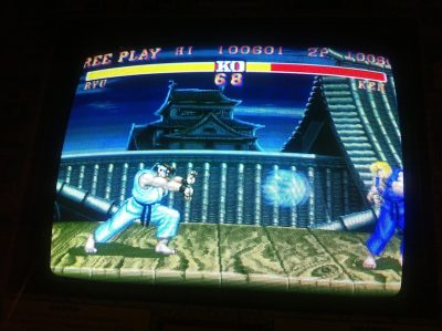
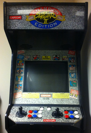
I’ve started investigating the Street Fighter 2: Champion Edition arcade machine and here’s what I’ve found so far.

Power Supply Is Good

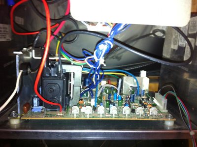
The first thing you’ll want to check on an arcade board is the power supply. I took my multimeter and measured the voltage on the JAMMA connector part of the board. At first I read a higher than normal reading. The pc board should be getting +5V and +12V from the power supply. What I measured instead was +6.4V and +14V.

I turned down the knob on the power switching supply until I got around +5.6V. I was still getting +14V out of it instead of +12V. I figured I’d need a new power supply. The next day, however, I tried measuring some batteries and found my multimeter was reading them high, too. I got a different multimeter with fresh batteries in it and in the end, I was getting proper readings. I adjusted it back up to around +5V (and +13V), and it’s good. I figure the +13V should be okay as I’ve read it’s mostly only used by the audio system and it should be okay with that.

Next: Check the pc board

The next thing to try is looking at the printed circuit board, i.e. the game circuit board itself. The PCB is actually in really good shape. It’s very clean and feels like new. Here’s a picture of it without Board C (the top one) attached.

sf2ce-board-b
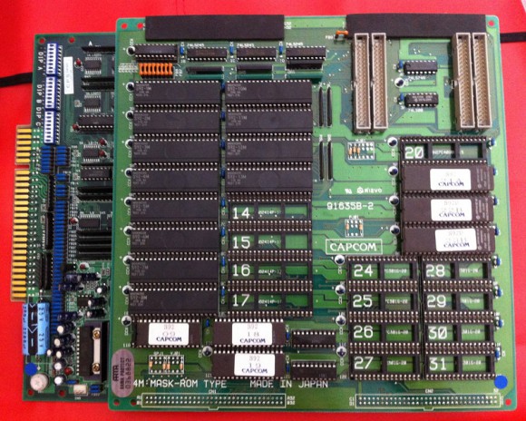
I split up all three boards, A, B, and C. I inspected each one and I actually found a nice little broken trace on board B:

broken
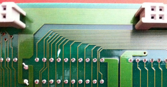
I tested both ends of it with the multimeter and verified it was definitely open. I got a wire and soldered it to both ends to bridge the gap:

bridged
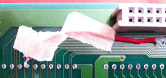
I tested both ends again with the multimeter and it seems good. In this case, it was line 6 of the D bus connector. I traced it to its intended receiver on board B. One of the PAL chips wasn’t receiving this input, so who knows what kinds of errors that was causing.

I looked at board C and also noticed another knick on one of the traces, but according to the multimeter, it isn’t a broken.

Check the ICs

After inspecting for broken traces, I took a quick look at the socketed ICs. I pulled out a few and reseated them, but for the most part, I couldn’t really see any issues with bad pins or whatnot. It’s still possible some have oxidized pins, so I may try reseating the lot of them if it still doesn’t work.

Now what?

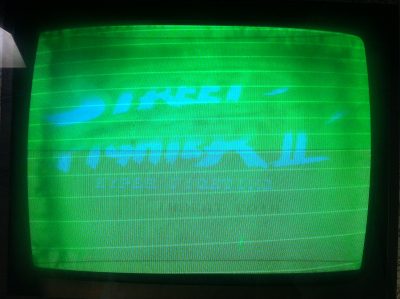
I don’t have the arcade cabinet at home with me where I did this work, so I still don’t know if bridging the above made it any better. After inspecting the board closely, I did notice the potentiometer in the bottom-left corner of Board A. That’s the volume for the speakers. I wasn’t hearing any audio last time I turned on the cabinet, so I’ll try turning that up and seeing if I hear anything next time.

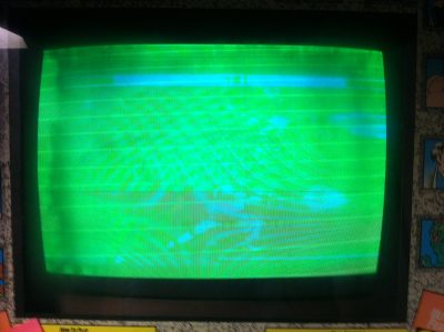
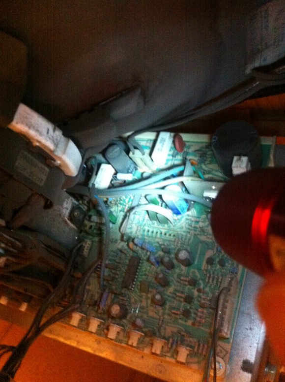
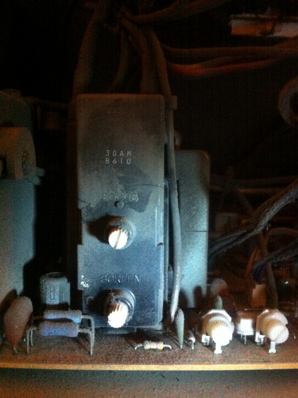
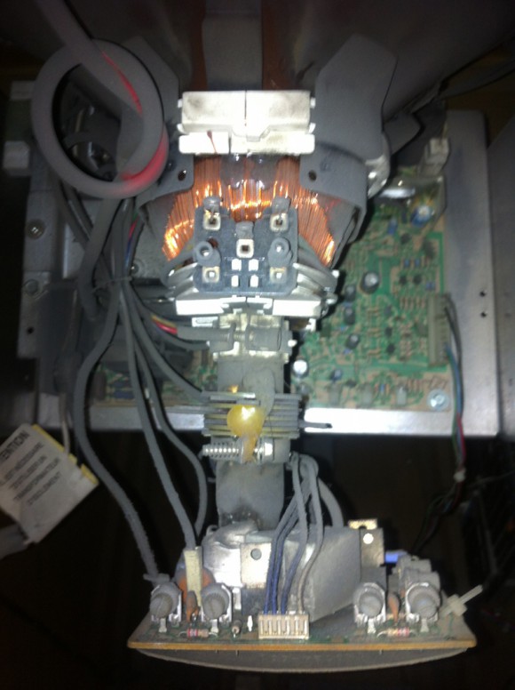
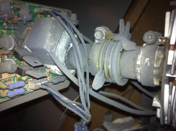
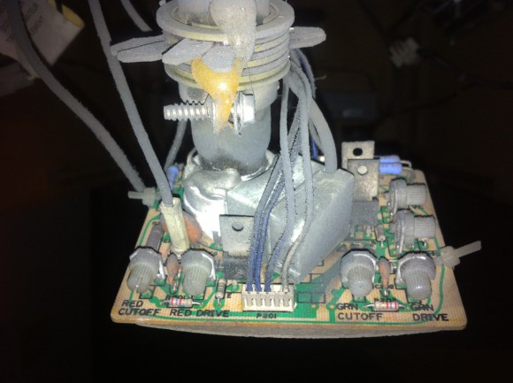
One thing that concerns me next is the monitor. After looking some pictures I took of the thing and comparing with pictures of monitors online, I’ve determined it’s a Wells Gardner K7000 monitor.

Apparently, this monitor typically has some real problems with the “flyback”, so I may have to look into that should nothing yet work.

Try out a working board

I ordered a Street Fighter II: Turbo Hyper Fighting JAMMA board off eBay a few days ago and it came in the mail yesterday. I’ll try that out in the machine. The funny thing about this board is that it is in much worse-looking condition than the Champion Edition board I have now. However, the eBay seller advertised that it worked, so it had better. The Hyper Fighting board has some real nasty dust on it and a lot of the parts just look worn. The CE board in comparison looks brand new.

If the Turbo board also does not work in the cabinet, most likely there is something wrong with the monitor and/or audio. Here’s hoping it does work, though, so I can at least narrow in on the CE board.