Re-capping a Commodore 1702 monitor

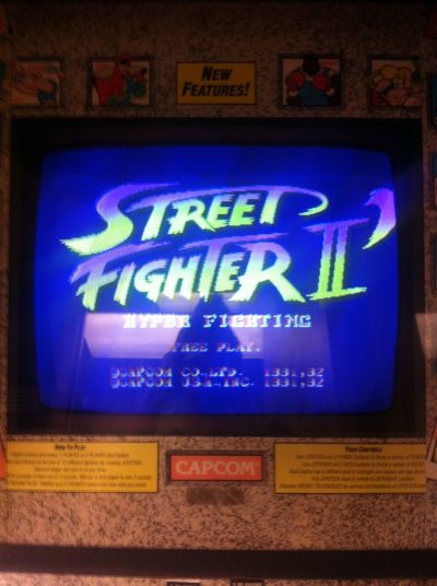
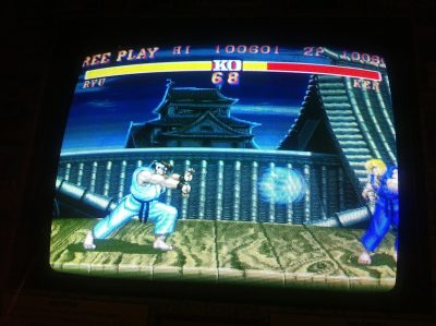
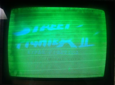
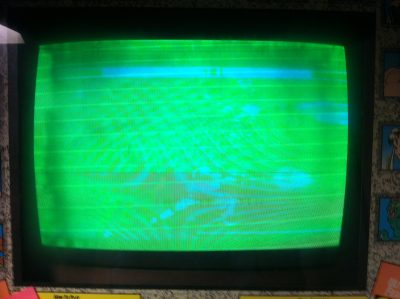
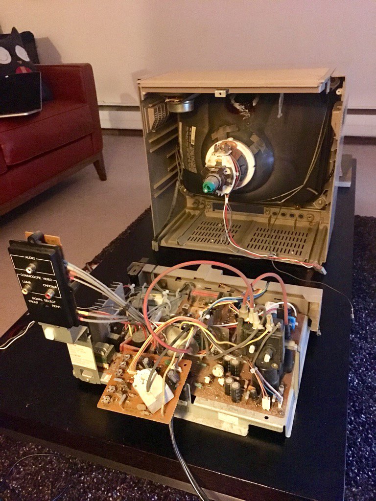
I’ve got a Commodore 1702 monitor and it’s been flickering a lot lately. It’s high time for a re-cap. I’ve got a cap kit and am ready to go.

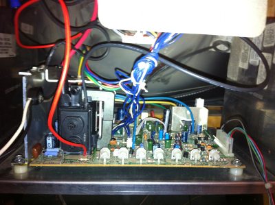
I opened it up and this is what it looks like on the inside. Note: it has a lot of capacitors, so I’ll have to do this over several sessions as soldering is a laborious process. šŸ™

c32q-hvucaeec1k

If you’re doing a re-cap of a 1702, here’s a good diagram of all the capacitors. I bought my cap kit from Console5.

Some quick notes about opening up the Commodore 1702:

  • There a bunch of screws in the back. After unscrewing all of them (including the ones near the rear inputs), store them all together somewhere. They’re all the same.
  • There are three screws in the front. Store these together. They’re different from the back ones.
  • Pull apart the front and back plastic frame carefully.
  • Next, discharge the cathode ray tube for safety. Please look up how to do this online. It’s very important as you don’t want to zap yourself. The CRT can store thousands of volts even when unplugged!
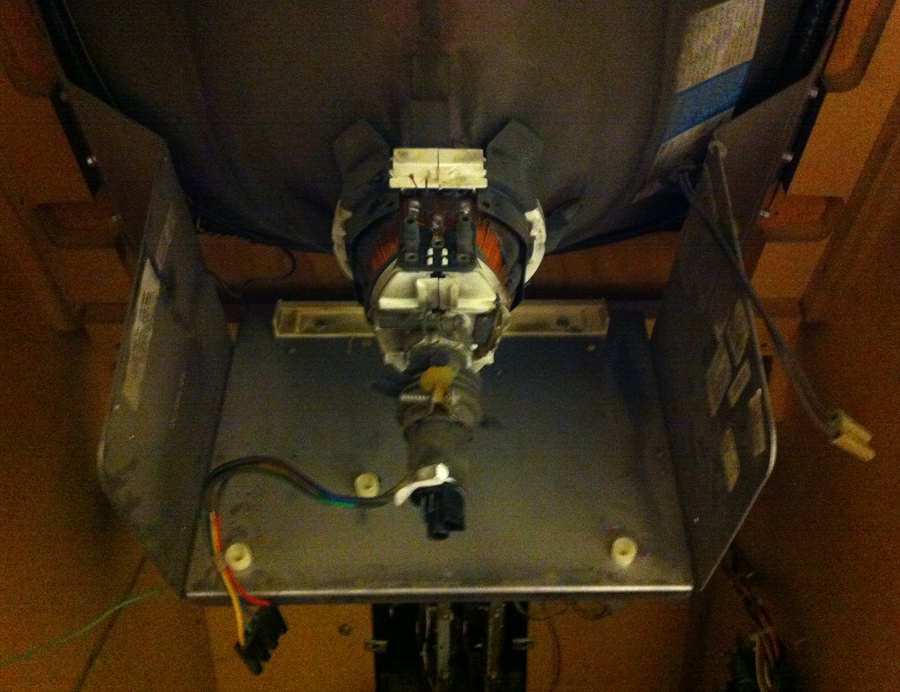
  • After discharging the CRT, slowly pull the CRT neck PCB off the neck tube. You’ll need to slowly wiggle it backwards to get it off.
  • Remove the flyback transformer “suction cup” from the top of the CRT.
  • Unplug the groundĀ wireĀ from the neck PCB.
  • Unplug the speaker wires.
  • Unplug the three-wire input (sorry, don’t know the term for this) coming from the CRT into the mainĀ chassis PCB.
  • Unplug the two-wire input input (don’t know this term either) from the CRT going into the main chassis PCB.

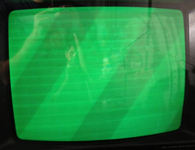
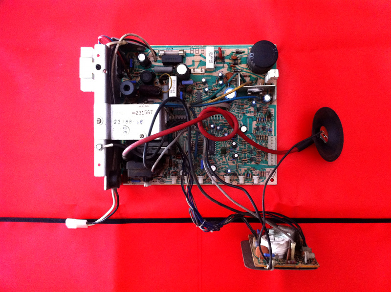
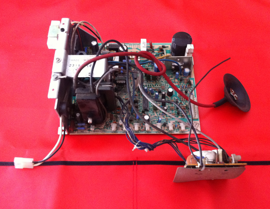
After doing the above, you can separate the chassis PCB from the CRT itself. This is what you see in the picture above.

For me, the next step is to de-solder, remove, and replace each capacitor from all the boards. I’ll do this one by one so I don’t get lost. (Removing all of them at once wouldĀ lead to confusion when replacing them. I’d have to constantly look at the diagram!) I’m not sure yet if it’s better to unscrew the chassis PCB from the frame or if I can just work on it directly. We’ll see.

More updates coming soon!

Fixed the Street Fighter II CRT!!

A month and a half ago, I got a free SF2 machine. However, it was putting out a green screen. Since that time I’ve been repairing the display and today I finally had a real breakthrough.

Somebody at work had a B&K 467 Rejuvenator device and came by to my office today. He gave the ol’ K7000 monitor on my arcade machine a nice rejuvenation and now the SFII arcade machine is functional!

In the end, there was definitely a short in the green gun, which we cleared using the rejuvenator. There was also likely a small short in the blue gun. The blue gun was fairly weak, so we boosted that up. The red gun was very weak, so that improved the most. The rejuvenator device really came through in this one and in the end I was right about it being a CRT issue and not some issue with the chassis.

The next step is to replace the joysticks and buttons. The left joystick is missing a switch, so the player can’t walk forward. Both joysticks are a little worse for wear in general (squeaky and hard to rotate), so I’m going to replace them both. I also need to replace the fluorescent bulb in the marquee. After that gets replaced, it’s gonna look super classy.

If you haven’t been following along, check outĀ all the blog posts about this arcade machineĀ that I got for free.

A Heater-Cathode Short

Last time I posted, I mentioned that I installed a new cap kit, new flyback, and new HOT on the arcade monitor. However, it was still giving me a green image. Here’s a video of what it looks like:

After some investigations online, I’ve come to the conclusion that it’s a heater-cathode short. What is that exactly?

Every CRT monitor has three electron guns, one for each of the three color components, red, green, and blue. These electron guns fire electrons from the back of the set to the screen, lighting up phosphor, which glows either of the three colors. The electron guns are located inside a vacuum tube and are aided by a heating element. The heating element heats up something called a cathode, where the electrons originate.

The problem is this: if debris collects on the cathode and comes in contact with the heating element you get a “short” in the circuit, which causes the electrons to always fire, even when they shouldn’t be. For instance, if the green gun has a short, instead of firing only when there are green elements in the pixel, it will always fire. I suspect that’s what’s happening with my screen.

To fix it, I’ve read that you can try plugging a CRT rejuvenator device into the back of the set. What this thing will do is send higher than normal levels of voltage through the electron guns, hopefully burning off the collected debris found in the short. After you burn off the debris, no more short.

A Gallery of Heater-Cathode Shorts

What I found interesting online is that there are very few posts with pictures of this heater-cathode short phenomenon, so I decided I should post some links below in case someone googles this info in the future.

First off, this guy encountered it with his NARC machine and got a green screen very similar to mine above.

narc

Someone else has a bad gun on their vertical setup.anothergreen

The red gun can also be shorted, as seen by this guy’s Golden Tee machine.goldenteeMore red screen madness on this Mortal Kombat machine.

redscreenYet another red gun shorted.

yetanotherred

It May Not Be Heater-Cathode Short

Sometimes you may have a problem in your neck board or the monitor chassis and it may not be a heater-cathode short. To check for this, the general advice I’ve seen is to try check your neck board. The neck board has similar circuits for each of the three color components. If you have a problem, it may be a bad transistor. To test this theory, simply swap transistors between two colors. For instance, if you see too much green on the screen, try swapping the green transistor with the red one and see if the problem becomes too much red on the screen. If it is, then most likely you have a bad transistor.

K7000 Chassis Repair: Installed a cap kit, new flyback, and new HOT

arcademachine

If you’re just joining us, a few weeks ago, I got a free, yes, free, Street Fighter II: Champion Edition arcade machine. I turned it on and found there was no sound and the screen was all green. Since then, I’ve determined the original arcade board (the PCB) was bad. However, the screen remains green, so I’ve been doing research to find out what exactly I need to fix on the CRT monitor to get it working again.

My monitor chassis is a Wells Gardner K7000 and on the advice of several people who have worked on monitor repair before, I was told to replace the capacitors, the flyback, and the Horizontal Output Transistor, i.e. the HOT.

Over the course of two late nights, I made the repairs. (Boy, I learned a lot. I’ll have a separate blog post on some tips for replacing the flyback and caps.) I put the monitor chassis back in the arcade machine today to see the results of my hard work.

Here she is after getting a new flyback, caps, and HOT. I cleaned up the PCB and wires as well, so she’s looking real clean:

installed

The good news is nothing blew up. I can also adjust the the screen enough that I can actually see some gameplay! The flyback is working much smoother. The old one had high pitched hiss. When compared against the YouTube video I took of this a few weeks ago, you can see that there are no more wavy vertical lines on the right. I suspect the replaced capacitors fixed this up.

The bad news is that it’s still green and still has horizontal lines. šŸ™ Actually it’s green with hints of blue. If I crank up the brightness or contrast, I see even more blue. This was what I was seeing before the repairs as well.

Here are a couple of pics:

titlescreen

fireball

In the end, I am happy with my work doing the cap kit and flyback repair. I can’t believe I actually did it. However, there’s still more work to be done, so stay tuned.

Monitor Chassis Removed

After a lot of reading up on safety precautions and watching a lot of YouTube videos on CRT monitor discharging, I took the plunge.

First, I made a discharge tool. I took a flathead screwdriver and soldered an insulated wire to its shaft. I took the other end of the wire and attached an alligator clip to it. I soldered this end as well. I wrapped both soldered connections in electrical tape. I neglected to take a photo of the thing, butĀ here’s a diagram of what it might look like if you used alligator clips on both ends of the wire:

CRT29

I delayed discharging the monitor for as long as I could just because I was chicken. Finally, in the middle of the afternoon, I figured I should do it. I clipped the alligator clip to the frame, put my free hand in my pocket, and then slowly inserted the screwdriver tip under the anode cup. I have to admit it was frightening.

I slowly inserted it closer to the leads of the anode and next thing you know, I can feel it hitting the leads. And yet, no pop. That was it. I discharged the monitor uneventfully.

I was a bit underwhelmed and also a little scared that maybe I did it wrong, so I tried again. Still, no pop. I decided to go for it and pry the anode out using the screwdriver. After a few seconds, I got it off. Nothing to it!

I made contact with the hole at the top of the tube to verify there was no more charge. I found none at all, so that was it. The last time I turned on the monitor was a week earlier, so I suspect it discharged itself in that time. I’ve heard that the Wells Gardner K7000s don’t really hold a charge for very long, so that’s likely part of it. Anyway, it was overall much easier than I thought. As this page says,

It’s a little frightening the first couple of times, but the thrill wears off.

In the end, here’s what the cabinet looks like without the monitor chassis:

EmptyMonitor

Here’s what the chassis looks like after removal:

RemovedChassisArt

A better view of it:

ChassisTwoThe next step is to inspect the board, fix bad solder joints, replace the flyback, and replace the capacitors.